12V DC to 220V 100W Inverter Circuit Diagram

12V DC to 220V 100W Inverter Circuit Diagram
12V DC to 220V 100W Inverter

This is 100W inverter circuit. It uses 4047 IC and IRF540 Mosfet instead of 2N3055 transistor. Power output is 100W from 2-3A transformer.

  • Digg
  • Del.icio.us
  • StumbleUpon
  • Reddit
  • RSS

500W Mos-Fet Power Inverter from 12V to 110V/220V

 500W Mos-Fet Power Inverter from 12V to 110V/220V

 500W Mos-Fet Power Inverter from 12V to 110V/220V

500W Mos-Fet Power Inverter from 12V to 110V/220V

This circuit will provide a very stable "Square Wave" Output Voltage. Frequency of operation is determined by a pot and is normally set to 60 Hz. Various "off the shelf" transformers can be used. Or Custom wind your own FOR BEST RESULTS. Additional MosFets can be paralleled for higher power. It is recommended to Have a "Fuse" in the Power Line and to always have a "Load connected", while power is being applied. The Fuse should be rated at 32 volts and should be approximately 10 Amps per 100 watts of output. The Power leads must be heavy enough wire to handle this High Current Draw!

  • Digg
  • Del.icio.us
  • StumbleUpon
  • Reddit
  • RSS

12V to +/- 30V DC to DC Converter circuit Diagram

 12V to +/- 30V DC to DC Converter circuit Diagram

12V to +/- 30V DC to DC Converter

This is a DC to DC converter for car power amplifier. 12V input generates +30V and -30V output for preamp or power amplifiers. Circuit uses SG3525 IC, Mosfets and switching power supply.

  • Digg
  • Del.icio.us
  • StumbleUpon
  • Reddit
  • RSS

Simple DC to AC Inverter Circuit Diagram

Simple DC to AC Inverter Circuit Diagram

Simple DC to AC Inverter

This DC to AC inverter circuit work based on unstable multi vibrator does. In this circuit, IC CD4047 is chosen as a heart of unstable multivibrator, because this IC type gives a complementary output that has opposite phase to another ( pin 10 and 11 as seen in Figure 1), and has 50 % duty cycle that satisfy to generate a pulse for inverter.

  • Digg
  • Del.icio.us
  • StumbleUpon
  • Reddit
  • RSS

DC13.8V to DC250V Inverter Circuit Diagram

DC13.8V to DC250V Inverter Circuit Diagram

DC13.8V to DC250V Inverter Circuit

I have done a lot of work with valves in recent years. For me valves have many advantages, least of all the price; since they are now "obsolete" it is quite easy to get hold of them for next to nothing at rally's and junk sales. I recently purchased a couple of hundred battery valves for less than SEK1 (US$ 0.15) each. The biggest problem with valves is the PSU needed to provide +250 vDC and 6.3 vAC for the filaments. The transformers are no-longer available at a reasonable price, but a pair of 12v-6v-0v-6v-12v mains transformers will do the job just as well. For portable use only one transformer is required together with a pair of power transistors such as 2N3055 etc.

  • Digg
  • Del.icio.us
  • StumbleUpon
  • Reddit
  • RSS

12V to 220V 100W Transistor Inverter Circuit Diagram

 12V to 220V 100W Transistor Inverter Circuit Diagram

12V to 220V 100W Transistor Inverter

12V to 220V 100W transistor based power inverter.

  • Digg
  • Del.icio.us
  • StumbleUpon
  • Reddit
  • RSS

500W 12 Volt to 220 Volt Inverter Circuit Diagram

 500W 12 Volt to 220 Volt Inverter Circuit Diagram

500W 12 Volt to 220 Volt Inverter

This is circuit Inverter 12VDC to 220V 50Hz 500W. It easy to make and low cost.

  • Digg
  • Del.icio.us
  • StumbleUpon
  • Reddit
  • RSS

12V to +-20V Automotive Power Converter

 12V to +-20V Automotive Power Converter Diagram

12V to +-20V Automotive Power Converter (for audio amplifier)

The limitation of car supply voltage (12V) forces to convert the voltages to higher in order to power audio amplifiers. In fact the max audio power x speaker (with 4 ohm impedance) using 12V is (Vsupply+ - Vsupply-)^2/(8*impedance) 12^2/32 = 4.5Watts per channel, that is laughable... For powering correctly an amplifier the best is to use a symmetric supply with a high voltage differential. for example +20 - -20 = 40Volts in fact 40^2/32 = 50 Watts per channel that is respectable. This supply is intended for two channels with 50W max each (of course it depends on the amplifier used). Though it can be easily scaled up or the voltages changed to obtain different values.

  • Digg
  • Del.icio.us
  • StumbleUpon
  • Reddit
  • RSS

Car 12V to 50V DC Converter Circuit Diagram

Car 12V to 50V DC Converter Circuit Diagram

Car 12V to 50V DC Converter Circuit Diagram

This circuit for Car audio input battery 12V to 50VDC, It use transistor and IC TL072.

  • Digg
  • Del.icio.us
  • StumbleUpon
  • Reddit
  • RSS

24V to 12V 400W DC Inverter Circuit

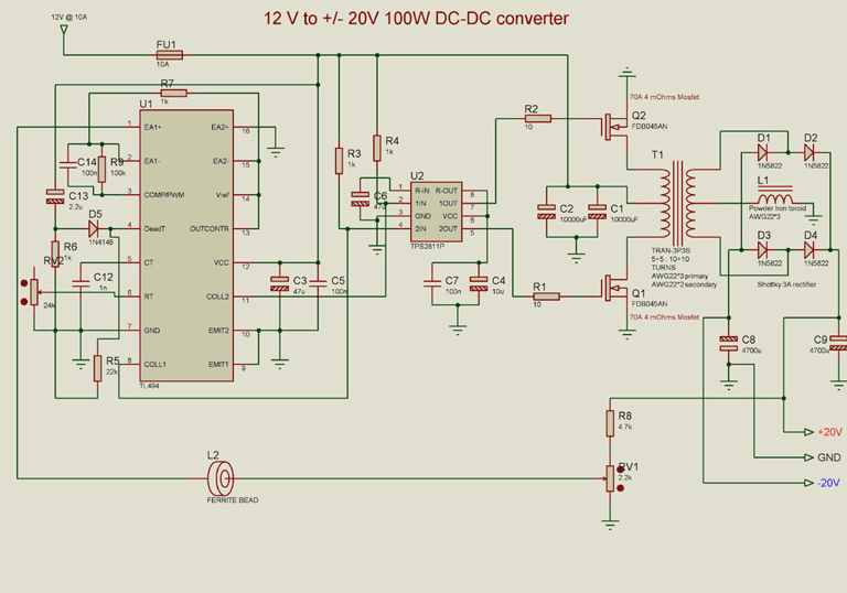
24V to 12V 400W DC Inverter Circuit Diagram
24V to 12V 400W DC Inverter Circuit

24V to 12V 20A 400W DC to DC Inverter. Does little to change my PV system 12v 24v me the problem arose of what to do with investors who already had 12V. I was looking for a pattern online and found several schemes with linear regulators 20A, this solution although quite simple, due to the huge losses they have is not advisable. Ideally, a converter switched, high-performance. At the end I found nothing I liked and decided to design my own. Circuit characteristics: Output current: 20A at 12V (15A continuous and 30A Momentary), Input voltage: 18 to 30V DC, Output voltage: 5 to 20V, Operating Frequency: 70kHz, Effectiveness: 95%, 400W maximum power, Protections: Above current (30A) in the F1 circuit, D1 and F1 polarity in the circuit.

  • Digg
  • Del.icio.us
  • StumbleUpon
  • Reddit
  • RSS

1.5V to 5V/12V DC/DC Converter with LT1073

 1.5V to 5V/12V DC/DC Converter with LT1073 Circuit
1.5V to 5V/12V DC/DC Converter with LT1073
Small 1.5V to 5V or 12V DC/DC converter with LT1073 chip. The IC is available in three different versions, depending on output voltage. Two with fixed output voltage of 5V and 12V, and the most interesting that can be adjusted. The adjustment is done through a voltage divider with two resistors, of mass, output and Terminal 8, internally connected to the voltage comparator IC, which is responsible for stabilizing the output voltage. 
 
1.5V to 5V/12V DC/DC Converter with LT1073

  • Digg
  • Del.icio.us
  • StumbleUpon
  • Reddit
  • RSS

Simple 500W 12V to 220V Inverter

500W 12V to 220V Inverter Circuit Diagram

500W 12V to 220V Inverter Circuit Diagram
 
This is a 500W DC-to-AC inverter circuit diagram which produces an AC output at line frequency and voltage. 12VDC to 220V 50Hz inverter circuit will power 220V or 110V appliances from 12V car battery. The circuit is easy to make and is low cost. Use proper transformer. The output (in watts) is up to you by selecting different power rating transformer and power transistor rating. If you load electronic device which require 120V AC, then use transformer with 120V in output.

  • Digg
  • Del.icio.us
  • StumbleUpon
  • Reddit
  • RSS