Cmos Motorcycle Alarm Circuit Diagram

This Simple Cmos Motorcycle Alarm Circuit Diagram features an intermittent siren output and automatic reset. It can be operated manually using a key-switch or a hidden switch; but it can also be wired to set itself automatically when you turn-off the ignition. By adding external relays you can immobilize the bike - flash the lights etc.

Cmos Motorcycle Alarm Schematic Diagram

Cmos Motorcycle Alarm Circuit Diagram

Notes
Any number of normally-open switches may be used. Fit "tilt" switches that close when the steering is moved or when the bike is lifted off its side-stand or pushed forward off its centre-stand. Use micro-switches to protect removable panels and the lids of panniers etc.

Once activated - the rate at which the siren switches on and off is controlled by R9 & C5. For example - increasing the value of C5 will slow it down - while reducing the value of R9 will make it faster.

While at least one switch remains closed the siren will sound. About thirty seconds after all of the switches have been opened, the alarm will reset. How long it takes to switch off depends on the characteristics of the actual components used. You can adjust the time to suit your requirements by changing the value of R6 and/or C4.

The circuit is designed to use an electronic Siren drawing 300 to 400mA. It's not usually a good idea to use the bike's own Horn because it can be easily located and disconnected. However, if you choose to use the Horn, remember that the alarm relay is too small to carry the necessary current. Connect the coil of a suitably rated relay to the "Siren" output. This can then be used to sound the Horn - flash the lights etc.

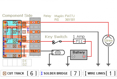
The circuit board and switches must be protected from the elements. Dampness or condensation will cause malfunction. Connect the 1-amp in-line fuse AS CLOSE AS POSSIBLE to your power source. This is VERY IMPORTANT. The fuse is there to protect the wiring - not the alarm. Exactly how the system is fitted will depend on the make of your particular machine - so I'm unable to provide any further help or advice in this regard.

The quiescent (standby) current of the circuit is virtually zero - so there is no drain on the battery. If you want to operate the alarm manually use a key-switch or a hidden switch connected to the "off/set" terminals. For automatic operation connect a wire from the ignition circuit to the "ignit" terminal. Then every time you turn-off the ignition - the alarm will set itself. Remember that this wire from the ignition switch is not protected by your 1-amp inline fuse. So unless its run is very short - fit the wire with its own 1-amp fuse as close as possible to its source.

When you set the alarm - if one of the switches is closed - the siren will sound. This could cause annoyance late at night. A small modification will allow you to Monitor The State Of The Switches using LEDs. When the LEDs are all off - the switches are all open - and it's safe to turn the alarm on.

Veroboard Layout

Cmos Motorcycle Alarm Circuit Diagram


  • Digg
  • Del.icio.us
  • StumbleUpon
  • Reddit
  • RSS

Power Pulse Using by LM350 and NE555

This is a Simple Power Pulse Using by LM350 and NE555 Circuit Diagram. This circuit can use to drive lamp,power LED,DC motor etc. Adjust R5 for output amplitude.Adjust R1 for output power .

Power Pulse Circuit Diagram

Power Pulse Circuit Diagram


The LM350 is adjustable 3-terminal positive voltage regulators is capable of supplying in excess of 3A over a 1.2V to 33V output range.This circuit requires 5-15V power supply.

  • Digg
  • Del.icio.us
  • StumbleUpon
  • Reddit
  • RSS

Nikon adds seven new cameras to the Coolpix range

Nikon adds seven new cameras to the Coolpix range

Nikon’s latest Coolpix cameras focus on durability and versatility, the waterproof, shockproof and freeze-proof AW120 leads the way 

Nikon has announced seven new Coolpix cameras sporting a variety of features to complement different lifestyles from rough and rugged to slim and stylish.

The Coolpix AW120 leads the pack with a 16-megapixel camera and is waterproof to 18m, shockproof to 2m and freeze-proof to -10°C for £329.99. 

Meanwhile the 13-megapixel Coolpix S32 is an easy-to-use camera that’s shockproof, dustproof and waterproof for an active family lifestyle for just £99.99.

The high performance entries on the lineup are the Coolpix P600 and super-zoom P530.

Both cameras are compact with high zoom power and include a built-in electronic viewfinder that allows you to snap photos on the move.

The Coolpix P600 will set you back £429.99 whilst the P530 costs £329.99.

Nikon has also released the stylish Coolpix S9700 and S9600 cameras with built-in WiFi so you can upload and share images via your smart device which can also act as a remote control for the camera.

The S9700 is priced £329.99 whilst the S9600 is cheaper at £249.99. 

The last of the lot is the compact 12-megapixel Coolpix P340 that also comes with built-in WiFi for £349.99.

Apart from the P530 that arrives on February 13, the Nikon Coolpix range will be available February 27.

  • Digg
  • Del.icio.us
  • StumbleUpon
  • Reddit
  • RSS

Sony to sell off PC business


Sony to sell off PC business


In a press statement released by Sony, the company said that it is selling off its VAIO brand and concentrate more on smartphones and tablets, citing “drastic changes in the PC industry”. Japan Industrial Partners (JIP) will take over the business, with the deal expecting to be completed by the end of July this year. 

The statement also said that Sony will “immediately cease planning, design and development of PC products”. It also said that manufacturing and sales will be discontinued after they release their Spring 2014 lineup. Sony also assured customers that they will still get after sales support even if the deal has been completed.

Always associated with elegant design, the VAIO line of notebooks has always been one of the preferred brands by some, including Steve Jobs – to which he even envisioned VAIOs running on Mac OS X.

  • Digg
  • Del.icio.us
  • StumbleUpon
  • Reddit
  • RSS

Samsung Galaxy S5 confirmed for MWC

 Samsung Galaxy S5 confirmed for MWC

While rumours have started to swirl over whether or not Samsung will reveal their much-anticipated Galaxy S5 smartphone at Mobile World Congress later this month, the organizing committee has confirmed that they will indeed.

Samsung recently sent out invitations to Samsung Unpacked 5, to be held at Mobile World Congress, and an accompanying video hinted that visitors might get a glimpse of the device. While it wasn’t confirmed, Mobile World Live confirmed the rumours.

“Samsung is set to launch its Galaxy S5 smartphone at Mobile World Congress this month, having announced its Unpacked 5 event will be held in Barcelona. The company will hold an event on the evening of Monday 24 February, marking the first time it has unveiled a flagship device at the event since the Galaxy S2 in 2011,” they said.

Late last year several media houses pegged the reveal around March with a consumer launch in April, but Mobile World Live said that the date has been brought forward – for several reasons. “The launch has been brought forward due to lower than expected sales of the Galaxy S4. Bringing the new device to market more quickly will enable it to reinvigorate its performance after a tough Q4.”

They added that the S5 would be one of the most important releases for Samsung. “The new flagship is especially important for Samsung’s position in the high-end smartphone market, where growth is hard to find and competition is fierce. In this space, the company has lost some momentum following Apple’s latest iPhone update.”

Charlie Fripp – Consumer Tech editor

  • Digg
  • Del.icio.us
  • StumbleUpon
  • Reddit
  • RSS

iPhones with Flappy Bird Pre-Installed Going for Sale

iPhones with Flappy Bird Pre-Installed Going for Sale

Selling on eBay for as much as $100,000 USD (367,000 AED).

The game Flappy Birds skyrocketed into the charts of app stores both on iOS and Android, and somehow created a fuzz for users everywhere. The game required you to simply tap on the screen to make the bird fly through obstacles but it is somehow met with frustration since most users can barely even get a score of one. The gameplay made it a trending topic on Twitter for days, along with everyone sharing their own scores and achievements.

Screen Shot 2014-02-10 at 5.32.50 PM

Even with the game pulling in about $50,000 on ad revenues per day, its maker, Dong Nguyen has had enough of it. Mentioning that "he can't take [the game's popularity] it anymore," he pulled out the game from the Apple App Store and on Google Play, so if you haven't downloaded it, you're out of luck.

Now, one user on eBay has decided to sell a used iPhone 5S with the game pre-installed. The catch? He is selling it for $99,900 USD (367,000 AED). At the time of writing, the phone now has 74 bids and a quick look at the seller's profile shows he has gotten positive feedbacks previously.

eBay tells us though that it may not ship in the United Arab Emirates, in case you are interested.

  • Digg
  • Del.icio.us
  • StumbleUpon
  • Reddit
  • RSS

1 W Home Stereo Amplifier Circuit Diagram

This is a one watt home stereo amplifier module project using the KA2209 IC from Samsung, which is equivalent to the TDA2822. It operates from 3-12V DC & will work from a battery since the dormant current drain is low. It requires no heat sink for normal use. The input & output are both ground referenced. Maximum output will be obtained with a 12V power supply & 8 ohm speaker, however it is suitable for driving headphones from a supply as low as 3V.

The Specifications of the home stereo amplifier :

D.C. input : 3 – 12 V at 200 – 500 mA max
Idle current : approx. 10 mA
Power output : > 1 Watt max. 4-8 ohms, 12V DC
Freq. Resp. : approx. 40 Hz to 200 kHz, 8 ohm, G=10
THD : < 1 % @ 750 mW, 4-8 ohm, 12V
Gain : approx. x10 (20 dB) OR x100 (40dB)
S/N ratio : > 80 dB, G = 20 dB
Sensitivity : < 300 mV, G = 20 dB
Input Impedance : approx. 10 k ohm

Description 

The gain is adjustable from ten to 100, i.e. twenty to 40 dB. Start with feedback resistors R1 and R3 of 1k ohm, this will give a gain of ten which ought to be adequate for most applications. In case you need more gain, you can remove resistors R1 and R3.This will give a gain of about 100, or 40 dB.The input attenuation can be adjusted by the potentiometer which can be used as a volume control. The IC gain ought to be kept as low as necessary to accomplish full output, with the in put potentiometer and your signal source at maximum.

1 W Home Stereo Amplifier Circuit Diagram

1 W Home Stereo Amplifier

Voltage Gain = 1+ R1/R2 = 1+R3/R4, however the maximum gain with no outside feedback is about 100, or 40dB. (GdB = 20log Gv)

This will keep the signal to noise ratio as high as feasible. Additional gain provided by the amplifier will reduce the S/N ratio by a similar amount, since the input noise figure is constant. Other values for R1 and R3 of between 1k and 10k ohm can be used if an intermediate gain level is necessary.

If driving a pair of headphones, you may also need a 100 ohm resistor in series with each output to reduce the output level, depending on headphone impedance & sensitivity. Make positive you start with the volume right down to check. Numerous headphones may be driven from the amplifier in the event you wish, since most headphones have at least 16 ohm impedance, or more often 32 ohm.

There are only a few outside parts, the IC contains most of the necessary circuitry. R1,R2 and R3,R4 are the feedback resistors. C1 provides power supply decoupling. C2 and C3 are the input coupling capacitors, which block any DC that might-be present on the inputs. C4,C5 block DC in the feed back circuit from the inverting inputs, and C6,C7 are the output coupling capacitors. C8, R5 and C9,R6 act as Nobel networks providing a high frequency load to maintain stability at frequencies where loud speaker inductive reactant may become excessive. The pot provides adjustable input level attenuation.

1 W Home Stereo Amplifier parts list

  • Digg
  • Del.icio.us
  • StumbleUpon
  • Reddit
  • RSS

PIC Security System Dials Your Cell Phone Circuit Diagram

This is a simple PIC Security System Dials Your Cell Phone Circuit Diagram. Do-it-yourself phone dialer security system calls your cell phone, office etc. whenever a door or window is opened, or panic button is pressed. Great Home Alarm.

PIC Security System Dials Your Cell Phone Circuit Diagram

PIC Security System Dials Your Cell Phone Circuit Diagram


The circuit consists of a small PIC microcontroller, assembly program, and a few other parts to detect a switch closure from an open door, window, or manual push button and then dial the cell phone number, and transmit a steady tone to indicate the source of the call. The circuit uses the pulse dialing system to interrupt the line connection a number of times to indicate each digit. Pulse dialing (the oldest form of dialing) works by actually disconnecting or "hanging up" the phone line a number of times to indicate each digit. For example, the digit "5" would be dialed by disconnecting and reconnecting the line 5 times in short intervals of about 100mS. There is about a 1 second pause (with the line connected) between each digit. The timing is not critical and I was able to dial 411 and connect to the local information service just using a momentary push button switch in series with the phone line.

Circuit Operation:
In operation, the switch closure is detected on pin 7 of the processor which activates the reed relay and takes the line off-hook for 3 seconds to establish the dial tone. The processor then dials the number by opening and closing the relay a number of times for each digit. When dialing is complete, the processor waits 3 seconds and then transmits a steady tone of about 300Hz for 30 seconds through the modem transformer. The call is then terminated and the processor waits for the switch to open before resetting.

Design Considerations:

The PIC16F628 (18 pin) processor was selected because I had a few on hand and my homemade hardware programmer only accepts 18 pin devices. A smaller 8 pin device could have been used since only three I/O lines are needed, but the difference in cost is only about $1.50. One of the I/O lines (RA5) is used for programming and is always an input, but can used as a functional input so the switch closure could be detected on this line thus eliminating the need for one pullup resistor. But I elected to use 3 consecutive I/O pins (7,8,9) of the 8 bit port B and leave RA5 pulled up with a extra 10K resistor.

The output pins (8,9) that drive the relay and transformer are limited to 25mA of current each, so an extra transistor (2N2222A) was needed to supply additional current to the relay coil. The transformer resistance is around 100 ohms, so an additional 330 ohm resistor was added in series with pin 9 to limit the transformer current to around 10mA. An LED indicator and 330 ohm resistor were used on pin 8 to observe the dialing activity and indicate the line status. Several of the parts (relay, transformer and blocking capacitor) were obtained from an old 56K modem card.

The schematic shows a 47uF / 50 volt non-polarized capacitor used to block DC current to the transformer, however a regular polarized 50uF cap could be used if correct phone line polarity is observed. The modem was probably designed to work with unknown polarities at different locations, so a non-polarized cap was used. It's possible the cap and 470 ohm resistor can be replaced with a single resistor in series with the line to set the "off hook" line current to around 20mA. This may cause partial saturation of the transformer and reduced audio level, but might work well enough.

The power supply voltage is not critical and a 4.5 volt supply from three AA batteries should work. Or a switching type regulated 5 volt wall transformer can be used. The problem is insuring the relay gets enough voltage to operate. The rest of the circuit should run on reduced voltage. I used a 4.2 volt cell phone charger that worked well.

  • Digg
  • Del.icio.us
  • StumbleUpon
  • Reddit
  • RSS

Simple 50W Electronic Amplifier Circuit Diagram

This Simple 50W Electronic Amplifier Circuit Diagram project is an IC amplifier module from ST Microelectronics, the TDA7294. It is intended for use as a top quality audio class AB amplifier in hi-fi applications. It's low noise and distortion, wide bandwidth and nice output current capability, enabling it to supply high power in to both four ohm and 8 ohm lots. It's both short circuit and thermal protection.

With the addition of a handful of parts and an appropriate power supply, this module will deliver over 50W RMS in to four or 8 ohms-with < 0.1% Total Harmonic Distortion (THD) and < 0.1% Inter-modulation Distortion (IMD). It is also suitable as a replacement power amp stage, or upgrade for plenty of existing amplifiers of between 30W-50W, provided they have an appropriate dual supply, & most do.

The Specifications of the electronic amplifier project there are:

D.C. Input : 35V
Output power : > 50W RMS, 4-8 ohm load.
Gain : 24 dB (30dB modification)
Input sensitivity : one.3V for 50W, 8 ohm
Signal-to-Noise ratio : > 95 dB, (>105 dBA)
Frequency response : approx. 20Hz - 200kHz, �3 dB
Slew rate : > 10V/uS
THD : < 0.01%, 1W-40W, 1kHz
IMD : < 0.01%, 1W

The maximum supply voltage of the IC is +/- 40V. However the maximum dissipation of the IC can be exceeded even at a lower voltage. Therefore the supply voltage used require not be over +/- 35V. This can be constructed using a 50V middle tapped-transformer, a diode bridge rated at 5A (min.) & a pair of electrolytic capacitors, as shown below. A lower secondary voltage transformer could even be used but the reduced DC voltage will lead to less power output in to 8 ohms. You can still receive 50W in to four ohms with only 24V supply rails.

A 36V C.T. transformer will give you approx +/- 25V rails. The-mains transformer used ought to be rated at a maximum of 80VA. In the event you require to run modules in a stereo amplifier you can use a common power supply. In this case the transformer ought to be rated at 150VA or greater.

 Simple 50W Electronic Amplifier Circuit Diagram


Electronic Amplifier Circuit Diagram Description

Most of the circuitry is contained within the IC module. The input signal is applied to pin three by capacitor C1 & low-pass filter R1/C2. The filter improves the pulse response & helps cease RF signals. The lower -3dB point is determined-by R2/C1 & R4/C3. This is about 20Hz for the values used. The upper -3dB point is over 200kHz. C7/C8 & C9/C10 provide additional power supply filtering or decoupling.

Simple 50W Electronic Amplifier Circuit Diagram


R3/R4 are the feedback resistors. The gain is 1+R3/R4 which is approx 16 times, or 24dB. In case you need to increase the input sensitivity you may alter the resistors to suit. Changing R3 to 22k would increase the gain to 30dB and lower the input-required for 50W in to 8 ohm, to 0.6V, without affecting performance much. In case you reduce the worth of R4 you will also need to increase C3 to maintain bass response, as this sets the feedback low frequency roll off.

Pin ten is a mute input and pin 9 provides a standby mode. Muting ought to always happen before standby mode is selected. Connecting these pins permanently to the supply rail ensures that the amplifier comes on immediately on power up. Any switch-on clicks may be eliminated by increasing the time constants of R5/C4 and R6/C5 if necessary.

Make definite that a heavy duty heat-sink rated at least one.4 degree C/W or better is used.

Simple 50W Electronic Amplifier Circuit Diagram

  • Digg
  • Del.icio.us
  • StumbleUpon
  • Reddit
  • RSS

Constructing your own Dual Power Supply Circuit

Many times the hobbyist desires to have a simple, dual power supply for a project. Existing power supplies may be large either in power output or physical size. a simple Dual Power Supply is necessary.For most non-critical applications the best & simplest choice for a voltage regulator is the 3-terminal type.The three terminals are input, ground & output.

The 78xx & 79xx series can provide up to 1A load current & it have on chip circuitry to prevent damage in the event of over heating or excessive current. That is, the chip basically shuts down than blowing out. These regulators are cheap, simple to make use of, & they make it practical to design a method with plenty of P C Bs in which an unregulated supply is brought in & regulation is done locally on each circuit board.

This Dual Power Supply project provides a dual power supply. With the appropriate choice of transformer & 3-terminal voltage regulator pairs you can basically build a tiny power supply delivering up to amp at +/- 5V, +/- 9V, +/- 12V, +/-15V or +/-18V. You require to provide the middle tapped transformer and the 3-terminal pair of regulators you require:7805 & 7905, 7809 & 7909, 7812 & 7912, 7815 & 7915or 7818 & 7918.

The user must pick the pair they needs for his particular application.

Note that the + & - regulators do not must be matched: you can for example, use a +5v & -9V pair. However,the positive regulator must be a 78xx regulator, & the negative a 79xx. They have built in plenty of safety in to this project so it ought to give plenty of years of continuous service.

Transformer
This Dual Power Supply design makes use of a full wave bridge rectifier coupled with a centre-tapped transformer. A transformer with a power output rated at at least 7VA ought to be used. The 7VA rating means that the maximum current which can be delivered without overheating will be around 390mA for the 9V+9V tap; 290mA for the 12V+12V and 230mA for the 15V+15V. If the transformer is rated by output RMS-current then the worth ought to be divided by one.2 to get the current which can be supplied. For example, in this case a 1A RMS can deliver 1/(one.2) or 830mA.

Rectifier
They use an epoxy-packaged four amp bridge rectifier with at least a peak reverse voltage of 200V. (Note the part numbers of bridge rectifiers are not standardised so the number are different from different manufacturers.) For safety the diode voltage rating ought to be at least to times that of the transformers secondary voltage. The current rating of the diodes ought to be two times the maximum load current that will be drawn.

Filter Capacitor
The purpose of the filter capacitor is to smooth out the ripple in the rectified AC voltage. There's dual amount of ripple is determined by the worth of the filer capacitor: the larger the worth the smaller the ripple.The two,200uF is an appropriate value for all the voltages generated using this project. The other consideration in choosing the correct capacitor is its voltage rating. The working voltage of the capacitor has to be greater than the peak output voltage of the rectifier. For an 18V supply the peak output voltage is one.4 x 18V, or 25V. So they have selected a 35V rated capacitor.

Regulators
The unregulated input voltage must always be higher than the regulators output voltage by at least 3V in order for it to work. If the input/output voltage difference is greater than 3V then the excess potential must be dissipated as heat. Without a heat sink three terminal regulators can dissipate about two watts. A simple calculation of the voltage differential times the current drawn will give the watts to be dissipated. Over two watts a heat sink must be provided. If not then the regulator will automatically turn off if the internal temperature reaches 150oC. For safety it is always best to make use of a small heat sink even in case you do not think you will need.

Stability
C4 & C5 improve the regulators ability to react to sudden changes in load current & to prevent uncontrolled oscillations.

Decoupling
The mono block capacitor C2 & C6 across the output provides high frequency decoupling which keep the impedance low at high frequencies.

LED
Two LED's are provided to show when the output regulated power is online. You do not must make use of the LED's in the event you do not require to. However, the LED on the negative side of the circuit does provide a maximum load to the 79xx regulator which they found necessary in the coursework of testing. The negative 3-pin regulators did not like a zero load situation. They have provided a 470R/0.5W resistors as the current limiting resistors for the LED's.

Diode Protection
These protect chiefly against any back emf which may come back in to the power supply when it supplies power to inductive lots. They also provide additional short circuit protection in the case that the positive output is connected by accident to the negative output. If this happened the usual current limiting shutdown in each regulator may not work as intended. The diodes will short circuit in this case & protect the two regulators.

Dual Power Supply Schematic Diagram


Dual Power Supply Schematic Diagram

  • Digg
  • Del.icio.us
  • StumbleUpon
  • Reddit
  • RSS

Motorcycle Alarm Circuit Diagram

This is a Motorcycle Alarm Circuit Diagram. Any number of normally open switches may be used. Fit the mercury switches so that they close when the steering is moved or when the bike is lifted off its side-stand or pushed forward off its center-stand. Use micro-switches to protect removable panels and the lids of panniers etc. While at least one switch remains closed, the siren will sound. 

 Motorcycle Alarm Circuit Diagram

Motorcycle Alarm Circuit Diagram


About tw1o minutes after the switches have been opened again, the alarm will reset. How long it takes to switch off depends on the characteristics of the actual components used. But, up to a point, you can adjust the time to suit your requirements by changing the value of C1.The circuit board and switches must be protected from the elements. Dampness or condensation will cause malfunction.Without its terminal blocks, the board is small. Ideally, you should try to find a siren with enough spare space inside to accommodate it. Fit a 1-amp in-line fuse close to the power source. 

This protects the wiring. Instead of using a key-switch you can use a hidden switch; or you could use the normally closed contacts of a small relay. Wire the relay coil so that it is energized while the ignition is on. Then every time you turn the ignition off, the alarm will set itself.When it`s not sounding, the circuit uses virtually no current. This should make it useful in other circumstances. For example, powered by dry batteries and with the relay and siren voltages to suit, it could be fitted inside a computer or any thing else that`s in danger of being picked up and carried away. The low standby current and automatic reset means that for this sort of application an external on/off switch may not be necessary.

Sourced by : Streampowers

  • Digg
  • Del.icio.us
  • StumbleUpon
  • Reddit
  • RSS

TV Audio Video Transmitter Schematic Diagram

This is a simple TV audio video transmitter circuit can be constructed using this schematic diagram . This TV audio video transmitter circuit can be used to transmit video signals from VCR ( or some other device ) to a TV without using any cable .

Video signals input at jack J1 are first terminated by resistor R6 and coupled through capacitor C1 to clamping-diode D1. Potentiometer R3 is used to set the gain of the video signal; its effect is similar to that of the contrast control on a TV set.


TV audio video transmitter Schematic Diagram

Bias-control R7 can be used to adjust the black level of the picture so that some level of signal is transmitted, even for a totally dark picture.

RF-transformer T1 and its internal capacitor form the tank circuit of a Hartley oscillator that's tuned to 4.5 megahertz. Audio signals input at J2 are coupled to the base of Q3 via C2 and R4: the audio signal modulates the base signal of Q3 to form an audio subcarrier that‚s 4.5-megahertz higher than the video-carrier frequency.

The FM modulated subcarrier is applied to the modulator section through C5 and R9.
Resistor R9 adjusts the level of the subcarrier with respect to the video signal.

Transistors Q1 and Q2 amplitude modulate the video and audio signals onto an RF-carrier signal. The operating frequency is set by coil L4, which is 3.5 turns of 24- gauge enameled wire on a form containing a standard ferrite slug.

The RF output from the oscillator (L4, C7 and C9 ) section is amplified by Q5 and Q6, whose supply voltage comes from the modulator . Antenna matching and low-pass filtering is performed by C12, C13, and L1.

Resistor R12 is optional; it is added to help match the output signal to any kind of antenna.
To align this audio video transmitter you need to tune a TV receiver to an unused channel between 2 and 6. The TV must have an indoor antenna connected directly to it; an outdoor antenna or cable won't work. Make sure both potentiometers (R3, R7) are in middle position and apply power to the transmitter. Adjust L4 with a nonmetallic tool until the TV screen goes blank ,then fine-adjust L4 for the "most-blank" picture.
Connect the video and audio outputs from a VCR(AV source) to jacks J1 and J2 (respectively) of the transmitter .

After that you should see a picture on the TV screen: if you do, readjust L4 for the best picture; if you don't, check the board for any bad connections. Next, adjust R3 for the best picture brightness and R7 for the best overall picture.

Finally, adjust T1 with a nonmetallic tool for the best sound .
The TV transmitter combines line level audio and video signals, and transmits the resulting signal up to 300 feet. The circuit can be powered from a 9-12V power supply circuit .

Sourced by: circuitsprojec

  • Digg
  • Del.icio.us
  • StumbleUpon
  • Reddit
  • RSS

Relay Based Motorcycle Alarm Circuit Diagrams

You can Make Relay Based Motorcycle Alarm Circuit Diagrams. You can use them to protect your motorcycle - but they have many more applications. If you use relays with 6-volt coils - they'll protect your "Classic Bike". Both alarms are very small. The completed boards occupy about half a cubic-inch - 8 cc. The standby current is zero - so they won't drain your battery.

Relay Based Motorcycle Alarm Circuit Diagram 1 uses a SPCO/SPDT relay - but you really only need to use a SPST relay. If you are going to use the veroboard layout provided - you'll need to use the style of relay specified. But you can build the alarm using whatever style of relay you have available.

Relay Based Motorcycle Alarm Circuit Diagram 1


Any number of normally-open switches may be used. Fit the mercury switches so that they close when the steering is moved or when the bike is lifted off its side-stand or pushed forward off its centre-stand. Use micro-switches to protect removable panels and the lids of panniers etc. When one of the trigger-switches is closed - the relay will energize and the siren will sound.

You can choose what happens next. If you build the circuit as shown, the siren will continue to sound until you turn it off - or until the battery is exhausted. But, if you leave out D3 - the siren will stop sounding immediately the trigger-switch is re-opened.

While you're within earshot of your machine - the former configuration is best. You can always turn off the alarm yourself. But if you are going to be away from your bike for any length of time - and you don't want to cause a nuisance - then the latter configuration is probably more suitable. If you include a SPST switch in series with D3 - you can select the behaviour that best suits the circumstances at any given time.

Relay Based Motorcycle Alarm Circuit Diagram 1a

Relay Based Motorcycle Alarm Circuit Diagram 1a


Relay coils and some sounders produce high reverse-voltage spikes that will destroy sensitive electronic components. D1 and D2 are there to short-circuit these spikes before they can do any damage. Although there is nothing in the alarm circuit itself that could be damaged - I have no idea what other electronic equipment might be connected to the same power supply. So I included the two diodes as a precaution. If you're satisfied that there's nothing on your bike that might be damaged in this way - you can leave out the two diodes.

Relay Based Motorcycle Alarm Circuit Diagram 2 uses a DPCO/DPDT relay - but you really only need to use a DPST relay. If you are going to use the veroboard layout provided - you'll need to use the style of relay specified. But you can build the alarm using whatever style of relay you have available.

Relay Based Motorcycle Alarm Circuit Diagram 2

Relay Based Motorcycle Alarm Circuit Diagram
 Any number of normally-open switches may be used. Fit the mercury switches so that they close when the steering is moved or when the bike is lifted off its side-stand or pushed forward off its centre-stand. Use micro-switches to protect removable panels and the lids of panniers etc. When one of the trigger-switches is closed - the relay will energize and the siren will sound.


You can choose what happens next. If you build the circuit as shown, the siren will continue to sound until you turn it off - or until the battery is exhausted. But, if you leave out the (yellow) solder-bridge in the top left-hand corner of the diagram - the siren will stop sounding immediately the trigger-switch is re-opened.

While you're within earshot of your machine - the former configuration is best. You can always turn off the alarm yourself. But if you are going to be away from your bike for any length of time - and you don't want to cause a nuisance - then the latter configuration is probably more suitable. Connect a SPST switch in place of the (yellow) solder-bridge - and you can select the behaviour that best suits the circumstances at any given time.

Relay Based Motorcycle Alarm Circuit Diagram 2 a
Relay Based Motorcycle Alarm Circuit Diagram 2

 Relay coils and some sounders produce high reverse-voltage spikes that will destroy sensitive electronic components. D1 and D2 are there to short-circuit these spikes before they can do any damage. Although there is nothing in the alarm circuit itself that could be damaged - I have no idea what other electronic equipment might be connected to the same power supply. So I included the two diodes as a precaution. If you're satisfied that there's nothing on your bike that might be damaged in this way - you can leave out the two diodes.

Whichever alarm you build - the circuit board and switches must be protected from the elements. Dampness or condensation will cause damage. Without the terminal blocks - the board is small. Ideally, you should try to find a siren with enough spare space inside to accommodate it. Fit a 1-amp in-line fuse as close as possible to the power source. This is Very Important. The fuse is there to protect the wiring - not the circuit board. Instead of using a key-switch you can use a hidden switch; or you could use the normally-closed contacts of a small relay. Wire the relay coil so that it's energized while the ignition is on. Then every time you turn the ignition off - the alarm will set itself.

When the alarms are not sounding - the circuits use no current. This should make them useful in other circumstances - where a power supply is not readily available. Powered by dry batteries - with the relay and siren voltages chosen to suit - the alarms could be fitted almost anywhere. 

Sourced By : Streampowers

  • Digg
  • Del.icio.us
  • StumbleUpon
  • Reddit
  • RSS

Battery Low Voltage Beeper Circuit

Simple Battery Low Voltage Beeper circuit provides an audible and visual low voltage warning for 12V battery powered devices. When the battery voltage is above the set point (typically 11V), the circuit is idle. If the battery voltage should fall below the set point, the LED will light and the speaker will emit a periodic beeping sound to warn of the impending loss of power. The circuit was designed for monitoring solar systems, but it could also be useful for automotive and other 12V applications.

Specifications:
  • Nominal operating voltage: 12V
  • Idle current: 6ma
  • Low Voltage Warning current: 15ma
Theory:
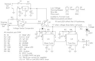
U2 provides a 5V regulated voltage reference. U1 is wired as a comparator, it compares the fixed 5V regulated voltage to the voltage on the wiper of VR1, that is proportional to the 12V supply. When the supply drops below the set point, the output of U1 goes low, turning on Q1 and powering the beeper and the LED.

The beeper consists of U4, a tone generator, and U3, a low duty cycle pulse generator. The tone can be changed by adjusting R7, the beep rate can be changed by adjusting R5. A small amount of hysteresis is provided by R1 and the current through LED1 and the beeper, this separates the on and off points for the circuit.


Battery Low Voltage Beeper Circuit

Simple Battery Low Voltage Beeper circuit board was made by printing the pattern (see below) onto Press-n-peel blue circuit board transfer film with a laser printer. Etch the board, drill the holes, and assemble the parts on the board as per the board photo. Be sure to correctly orient the diode, electrolytic capacitors, ICs, and transistor. The CA3160 op-amp may be difficult to find, other low power CMOS op-amps may be substituted. A standard 741 op-amp would also work, but the idle current will be higher.

Alignment:
Connect the circuit to an adjustable DC voltage source. Set the voltage source to 11V or wherever you would like the circuit to turn on. Turn on switch S1. Adjust VR1 until the point where LED1 just comes on and the beeping starts.

Use:
Connect the circuit to the 12V source that you wish to monitor. There should be a fuse somewhere between the battery and this circuit. Turn S1 on, if the battery voltage is above the set point, nothing should happen.
As the battery voltage drops below the set point, the LED will light and a periodic beeping will come from the speaker. If the beeping becomes annoying, turn off S1. Be sure to charge the battery soon, excessive discharging will shorten the life of most rechargeable batteries.

  • Digg
  • Del.icio.us
  • StumbleUpon
  • Reddit
  • RSS

HiFi Expandor Circuit Diagram with De-emphasis

This is the schematic design of HiFi Expandor Circuit with De-emphasis. The circuit is based NE570. The NE570 can be used to construct a high performance compandor suitable for use with music. This type of system can be used for noise reduction in tape recorders, transmission systems, bucket brigade delay lines, and digital audio systems. The circuits to be described contain features which improve performance, but are not required for all applications.

HiFi Expandor Circuit  Diagram

The expandor to complement the compressor is shown in the above circuit. Here an external op amp is used for high slew rate. Both the compressor and expandor have unity gain levels of 0dB. Trim networks are shown for distortion (THD) and DC shift. The distortion trim should be done first, with an input of 0dB at 10kHz. The DC shift should be adjusted for minimum envelope bounce with tone bursts. When applied to consumer tape recorders, the subjective performance of this system is excellent.

  • Digg
  • Del.icio.us
  • StumbleUpon
  • Reddit
  • RSS

Homemade Fence Charger Energizer Circuit Explained

The electric fence charger circuit presented here is basically a high voltage pulse generator. The super high voltage is derived from a commonly used automobile ignition coil. An a stable multivibrator is used to generate the required frequency to drive the ignition coil. Another a stable is used to control the pulses supplied to the fence.

 If you have large agricultural fields and desperately need to protect the crops from uninvited guests like animals and possibly humans, then this electric fence charger device is just what you are looking for. Build and install it yourself. An electric fence is an electrified high voltage barrier which produces painful shocks if physically touched or manipulated. Thus such fencing basically function as deterrents for animals as well as human intruders and stop them from crossing the restricted boundary.

Build  A Homemade Fence Charger Energizer Circuit Explained

Build  A Homemade Fence Charger Energizer Circuit Explained


The present circuit of an electric fence charger is designed and tested by me and has proved sufficiently powerful for the application. The circuit is able to produce voltage pulses up to 20,000 volts, needless to say about the fatality rate involved with it. However the pulses being intermittent, provides the subject with enough time to realize, recover and eject.

The generated pulse is so powerful that it can easily arc and fly-off between short distances of around a cm. so the fencing conductor needs to be separated adequately to avoid leakages through arcing and sparking. If not tackled, may drastically reduce the effectiveness of the unit.

Here the generation of high voltage is primarily carried out by an automobile ignition coil.

The winding ratios of an ignition coil are specifically designed and intended for creating high voltage arc between a two closely spaced conductors inside the ignition chamber to initiate the ignition process in vehicles.

Basically it’s just a step-up transformer, which is able to step-up an input applied voltage at its primary winding to monstrous levels at its output or the secondary winding.

SOME POINTS OF THE CIRCUIT AND THE IGNITION COIL IS VERY DANGEROUS TO TOUCH WHEN POWERED. ESPECIALLY THE IGNITION COIL OUTPUT IS TOO LETHAL AND MAY EVEN CAUSE PARALYSIS.

Let’s diagnose the whole thing more deeply.

Circuit Description


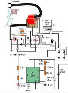
In the CIRCUIT DIAGRAMwe see that the entire circuit is basically comprised of four stages.

A DC oscillator stage, An intermediate 12 to 230 volts step-up stage, The voltage collector and firing stage and The super high voltage-booster stage.

 TR1 and TR2 are two normal step-down transformers whose secondary windings are connected through SCR2. TR2’s input primary winding may be selected as per the country specification.

However, TR1’s primary should be rated at 230 volts.

IC1 along with the associated components forms a normal astable multivibrator stage. The supply voltage to the circuit is derived from the secondary of TR2 itself.

The output from the astable is used to trigger SCR2 and the whole system, at a particular fixed intermittent rate as per the settings of P1.

During the ON periods, SCR2 connects the 12 volt AC from TR2 to the secondary of TR1 so that a 230 volt potential instantly becomes available at the other end of TR1.

 This voltage is fed to the voltage-firing stage consisting of the SCR1 as the main active component along with a few diodes, resistor and the capacitor C4.

The fired voltage from SCR1 is dumped into the primary winding of the ignition coil, where it is instantly pulled to a massive 20,000 volts at its secondary winding. This voltage may be suitably terminated into the fencing.

The high voltage generated by this electric fence charger will need to be carefully applied across the whole length of the fence.

The two poles from the ignition coil connected to the fence wiring should be kept at least 2 inches apart.

 The pillars of the fence should be ideally made of plastic or similar non conducting material, never use metal and not even wood (wood tend to absorb moisture and may give path to leakages).

 Parts List

R4 = 1K, 1WATT,
R5 = 100 OHMS, 1WATT,
P1 = 27K PRESET
C4 = 105/400V PPC,
ALL DIODES ARE 1N4007,
IC = 555
TR1 = 0-12V/3Amp (120 or 230V)
TR2 = 0-12V/1Amp (120 or 230V)
BOTH THE SCRs ARE C106 OR PREFERABLY BT151,

TWO WHEELER IGNITION COIL IS SHOWN IN FLUORESCENT BLUE COLOR


Author Swagtam

  • Digg
  • Del.icio.us
  • StumbleUpon
  • Reddit
  • RSS

Electronic Security Door Key Circuit Diagram

A different Electronic Security Door Key Circuit Diagram of electronic lock very simple, one and does not need a lot of materials in order to it is manufactured. The right keys of code should be stepped with the right line, so that is activated the optocupler IC2. If from error is stepped switch that does not belong in the combination, then the lock is trapped. In order to we restore the regular operation of lock, it should we press switches S1 or S12. 


Electronic Security Door Key Circuit Diagram


Switch S1 makes Reset of lock externally and the S12 internally, the door. The Code the circuit as he is connected it is 147 and it can change, very easily, changing the connections in the switches of keyboard. The optocupler IC2, can drive any exterior circuit as Relay etc, ensuring simultaneously electric isolation the two circuits. The circuit can be also supplied from a battery 9V.

Part List

    R1-7-9=1Kohm
    R2-3-4-5=100Kohm
    R6 =10Kohm
    R9 =47Kohm
    IC1 = 4066
    IC2 =4N25
    Q1-2=BC550
    S1...11=Push button sw or keyboard
    S12=Push button normal closed
    All resistors is 1/4W 5%

  • Digg
  • Del.icio.us
  • StumbleUpon
  • Reddit
  • RSS

10 W Audio Amplifier Circuit Diagram

This design is based on the 18 Watt Audio Amplifier, and was developed mainly to satisfy the requests of correspondents unable to locate the TLE2141C chip. It uses the widespread NE5532 Dual IC but, obviously, its power output will be comprised in the 9.5 - 11.5W range, as the supply rails cannot exceed ±18V.


10 W Audio Amplifier Circuit Diagram


As amplifiers of this kind are frequently used to drive small loudspeaker cabinets, the bass frequency range is rather sacrificed. Therefore a bass-boost control was inserted in the feedback loop of the amplifier, in order to overcome this problem without quality losses. The bass lift curve can reach a maximum of +16.4dB @ 50Hz. In any case, even when the bass control is rotated fully counterclockwise, the amplifier frequency response shows a gentle raising curve: +0.8dB @ 400Hz, +4.7dB @ 100Hz and +6dB @ 50Hz (referred to 1KHz).

Notes:

  • Can be directly connected to CD players, tuners and tape recorders.
  • Schematic shows left channel only, but C3, C4, IC1 and the power supply are common to both channels.
  • Numbers in parentheses show IC1 right channel pin connections.
  • A log type for P2 will ensure a more linear regulation of bass-boost.
  • Do not exceed 18 + 18V supply.
  • Q3 and Q4 must be mounted on heatsink.
  • D1 must be in thermal contact with Q1.
  • Quiescent current (best measured with an Avo-meter in series with Q3 Emitter) is not critical.
  • Set the volume control to the minimum and R3 to its minimum resistance.
  • Power-on the circuit and adjust R3 to read a current drawing of about 20 to 25mA.
  • Wait about 15 minutes, watch if the current is varying and readjust if necessary.
  • A correct grounding is very important to eliminate hum and ground loops. Connect to the same point the ground sides of J1, P1, C2, C3 &C4. Connect C9 to the output ground.
  • Then connect separately the input and output grounds to the power supply ground.

Parts:

P1_________________22K   Log.Potentiometer (Dual-gang for stereo)
P2________________100K Log.Potentiometer (Dual-gang for stereo)
R1________________820R 1/4W Resistor
R2,R4,R8____________4K7 1/4W Resistors
R3________________500R 1/2W Trimmer Cermet
R5_________________82K 1/4W Resistor
R6,R7______________47K 1/4W Resistors
R9_________________10R 1/2W Resistor
R10__________________R22 4W Resistor (wirewound)

C1,C8_____________470nF 63V Polyester Capacitor
C2,C5_____________100µF 25V Electrolytic Capacitors
C3,C4_____________470µF 25V Electrolytic Capacitors
C6_________________47pF 63V Ceramic or Polystyrene Capacitor
C7_________________10nF 63V Polyester Capacitor
C9________________100nF 63V Polyester Capacitor

D1______________1N4148 75V 150mA Diode

IC1_____________NE5532 Low noise Dual Op-amp

Q1_______________BC547B 45V 100mA NPN Transistor
Q2_______________BC557B 45V 100mA PNP Transistor
Q3_______________TIP42A 60V 6A PNP Transistor
Q4_______________TIP41A 60V 6A NPN Transistor

J1__________________RCA audio input socket

Power supply parts:

R11_________________1K5  1/4W Resistor

C10,C11__________4700µF 25V Electrolytic Capacitors

D2________________100V 4A Diode bridge
D3________________5mm. Red LED

T1________________220V Primary, 12 + 12V Secondary 24-30VA Mains transformer

PL1_______________Male Mains plug

SW1_______________SPST Mains switch
 

Technical data:

Output power:
10 Watt RMS into 8 Ohm (1KHz sinewave)
Sensitivity:
115 to 180mV input for 10W output (depending on P2 control position)
Frequency response:
See Comments above
Total harmonic distortion @ 1KHz:
0.1W 0.009% 1W 0.004% 10W 0.005%
Total harmonic distortion @ 100Hz:
0.1W 0.009% 1W 0.007% 10W 0.012%
Total harmonic distortion @ 10KHz:
0.1W 0.056% 1W 0.01% 10W 0.018%
Total harmonic distortion @ 100Hz and full boost:
1W 0.015% 10W 0.03%
Max. bass-boost referred to 1KHz:
400Hz = +5dB; 200Hz = +7.3dB; 100Hz = +12dB; 50Hz = +16.4dB; 30Hz = +13.3dB
Unconditionally stable on capacitive loads
 

  • Digg
  • Del.icio.us
  • StumbleUpon
  • Reddit
  • RSS

Auto Anti-Hijack Alarm Circuit Diagram

This Auto Anti-Hijack Alarm Circuit Diagram was designed primarily for the situation where a hijacker forces the driver from the vehicle. If a door is opened while the ignition is switched on - the circuit will trip. After a few minutes delay - when the thief is at a safe distance - the Siren will sound.

Auto Anti-Hijack Alarm Circuit Diagram

Where it differs from the first two alarms - is in what happens next. I'm obliged to Victor Montanez from the USA who suggested that the engine cut-out should not operate - until the vehicle comes to a stop. That way - the engine will not fail suddenly or unexpectedly. And the hijacker will retain control.

I haven't been able to implement Victor's excellent suggestion completely - because I couldn't think of a simple, reliable and universally applicable way of sensing when the vehicle has come to a stop.

Instead - I have postponed engine failure until the ignition is switched off. Once the thief turns off the ignition - the engine will not re-start. Clearly - there is no certainty as to when this will occur. But I think it will occur sooner rather than later. Because there's a strong possibility that the hijacker will turn off the ignition - in an attempt to silence the siren. 

 Auto Anti-Hijack Alarm Circuit Diagram

Auto Anti-Hijack Alarm Circuit Diagram


As well as acting as a Hijack Alarm - this circuit offers some added protection. Like the Enhanced Hijack Alarm - it incorporates Jeff Chia's suggestion. That is - every time the ignition is switched on - the alarm will trip. So it will protect the vehicle whenever you leave it unattended with the ignition switched off - even overnight in your driveway.

Importance
Before fitting this or any other engine cut-out to your vehicle - carefully consider both the safety implications of its possible failure - and the legal consequences of installing a device that could cause an accident. If you decide to proceed - you will need to use the highest standards of materials and workmanship.

Notes
You're going to trip this alarm unintentionally. When you do - the LED will light and the Buzzer will give a short beep. The length of the beep is determined by C4. Its purpose is to alert you to the need to push the reset button. When you push the button - the LED will switch-off. Its purpose is to reassure you that the alarm has in fact reset. 

If the reset button is not pressed then - about 3 minutes later - both the Siren and the Buzzer will sound continuously. The length of the delay is set by R8 & C5. For extra effect - fit a second siren inside the vehicle. With enough noise going on - you may feel that it's unnecessary to fit the engine cut-out. In which case - you can leave out C7, D8, R12, R13, Ty1 & Ry2.

When the ignition is switched on - C3 & R4 are responsible for tripping the alarm. By taking pin 1 low momentarily - they simulate the opening of a door. If you don't want the alarm to trip every time you turn on the ignition - simply leave out C3 & R4. 

Because the voltage on C3 may be reversed - the capacitor needs to be non-polarized. But connecting two regular 22uF capacitors back to back as shown - will work just as well. Because non-polarized capacitors are not widely available - the prototype was built using two polarized capacitors.

To reset the circuit you must - EITHER turn off the ignition - OR close all of the doors - before you press the reset button. While BOTH the ignition is on - AND a door remains open - the circuit will NOT reset.

The reset button carries virtually no current - so any small normally-open switch will do. Eric Vandel from Canada suggests using a reed-switch hidden behind (say) the dash - and operated by a magnet. I think this is an excellent idea. As Eric said in his email: - "... that should keep any thief guessing for a while."

Veroboard Layout

Veroboard Layout
 
How you prevent the engine from starting is up to you. It should happen when Ry2 de-energizes. The contacts of Ry2 are too small to do the job themselves. So use them to switch the coil of a larger relay. Remember that the relay must be suitable for the current it's required to carry. Choose one specifically designed for automobiles - it will be protected against the elements - and will give the best long-term reliability. You don't want it to let you down on a cold wet night - or worse still - in fast moving traffic!!! Remember also that you must fit a 1N4001 diode across YOUR relay's coil - to prevent damage to the Cmos IC
YOUR relay should drop-out when Ry2 de-energizes. Wire YOUR relay so that when it drops-out the engine will not start. Because turning-off the ignition will cause both Ry2 and YOUR relay to de-energize - the standby current will be low - and the engine will be disabled while the vehicle is parked.
The circuit board must be protected from the elements. Dampness or condensation will cause malfunction. Fit a 1-amp in-line fuse AS CLOSE AS POSSIBLE to your power source. This is VERY IMPORTANT. The fuse is there to protect the wiring - not the components on the circuit board. Please note that I am UNABLE to help any further with either the choice of a suitable relay - or with advice on installation.
Both the Siren and the Buzzer will go on sounding until the alarm is reset. The circuit is designed to use an electronic Siren drawing up to about 500mA. It's not usually a good idea to use the vehicle's own Horn because it can be easily located and disconnected. However, if you choose to use the Horn, remember that Ry1 is too small to carry the necessary current. Connect the coil of a suitably rated relay to the "Siren" output. This can then be used to sound the Horn.


  • Digg
  • Del.icio.us
  • StumbleUpon
  • Reddit
  • RSS

Simple 3000 Watts UPS Circuit Diagram

How to Build Simple 3000 Watts UPS Circuit Diagram. This is a Simple 3000 Watts UPS Circuit Diagram

Simple 3000 Watts UPS Circuit Diagram

Simple 3000 Watts UPS Circuit Diagram

  • Digg
  • Del.icio.us
  • StumbleUpon
  • Reddit
  • RSS

Precision full wave Rectifier Circuit Diagram

The circuit provides accurate full wave rectification. The output impedance is low for both input polarities, and the errors are small at all signal levels. Note that the output will not sink heavy current, except a small amount through the 10K resistors. Therefore, the load applied should be referenced to ground or a negative voltage. Reversal of all diode polarities will reverse the polarity of the output

Since the outputs of the amplifiers must slew through two diode drops when the input polarity changes, 741 type devices give 5% distortion at about 300 Hz.


Precision full wave Rectifier Circuit Diagram

Precision full wave Rectifier Circuit Diagram

  • Digg
  • Del.icio.us
  • StumbleUpon
  • Reddit
  • RSS

Steps AVR Programming a Best Chip

This is a complete AVR Tutorial, including avr programming in a very basic & organized way, We will go through by following items.
  • What is an AVR?
  • Using Mac and Windows
  • How AVR programming works
  • Choosing a programmer, to burn the code.
  • Using AVRDUDE

What is a micro-controller?

The best way to explain what a microcontroller is, is to start with your computer. Your desktop computer (or laptop) is comprised of multiple parts, a CPU (such as a Pentium or Celeron), some RAM, a hard disk, a keyboard and mouse and a monitor screen. Programs are stored on the hard disk and run on the CPU, with temporary data stored in RAM. You can run multiple programs at a time by having one ‘master program’ called an operating system (such as Linux, Windows or Mac OS X) and that master program keeps track of things for you.

AVR Programming Chip


AVR Programming

The AVR chip has components, too. It has a CPU, some flash storage, some RAM and some EEPROM, all in one little chip!. The CPU is just like the one in a computer, but its much simpler and not nearly as fast (what do you expect for $2.50?) The flash storage is just like the flash storage in your mp3 player or digital camera card, except its used to store programs. Its kinda like the hard disk of the microcontroller, except you can only read from it. The RAM is just like computer RAM. The EEPROM is kinda like flash except you cant run a program from it, but its used as long term storage. The EEPROM doesnt get erased when the chip loses power.

So, to recap: The AVR chip runs whatever program is stored in the flash, uses the RAM for temporary storage and the EEPROM for longer term storage.

Most computers have a 32-bit CPU running at 1GHz, with 1GB of RAM and 100 GB of storage. The kinds of micro-controllers discussed here run at 10MHz, have 1KB of RAM and 10KB of storage. (On the order of) However, their small size, lower power consumption and low cost make them an excellent choice for many projects!

  • Digg
  • Del.icio.us
  • StumbleUpon
  • Reddit
  • RSS