Showing posts with label Inverter. Show all posts

Simple Low-Power Inverter Circuit Diagram

Here is a simple low-power inverter that converts 12V DC into 230-250V AC. It can be used to power very light loads like window chargers and night lamps, or simply give shock to keep the intruders away. The circuit is built around just two ICs, namely, IC CD4047 and IC ULN2004.IC CD4047 (IC1) is a monostable/astable multivibrator. It is wired in astable mode and produces symmetrical pulses of 50 to 400 Hz, which are given to IC2 via resistors R1 and R2.

Simple Low-Power Inverter Circuit Diagram
 
Simple Low-Power Inverter Circuit Diagram

IC ULN2004 (IC2) is a popular 7-channel Darlington array IC. Here, the three Darlington stages are paralleled to amplify the frequencies received from IC1. The output of IC2 is fed to transformer X1 via resistors R3 and R4.Transformer X1 (9V-0-9V, 500mA secondary) is an ordinary step-down transformer that is used here for the reverse function, i.e., step up. That means it produces a high voltage. Resistors R3 and R4 are used to limit the output current from the ULN to safe values. The 230-250V AC output is available across the high-impedance winding of the transformer’s primary windings.

Sourced By: EFY Author: Pradeep G.

  • Digg
  • Del.icio.us
  • StumbleUpon
  • Reddit
  • RSS

Build a 100 Watt Inverter Circuit Diagram

This is a 100 Watt Inverter Circuit Diagram with Veroboard Print (LOW COST). This 100 watt Inverter Circuit use Minimum number of Components.I think it is quit difficult to make a decent one like this with further less components.Here we use {CD 4047 IC} for generating the 100 Hz pulses and four {2N3055} Transistor for driving the load.The IC1 {CD 4047} wired as an Astable  multi vibrator produces two 180 degree out of phase 100 Hz pulse train.These pulse train are preamplifier by the two TIP122

100 Watt Inverter Circuit Diagram

Build a 100 Watt Inverter Circuit Diagram


Transistor.The output of the TIP122 Transistor are amplified by fout 2N3055 Transistor {Two transistor for each of half cycle} to drive the inverter transformer.The 220 AC be available at a secondary of the transformer.Nothing complex just the elementary inverter principle and the circuit great for small load like a few savers or fans.This is LOW COST inverter only 7 $.

Info
  •     12v Car Battery can be use for this Inverter Circuit.
  •     Use the P1 to set the output frequency  to 50 Hz.
  •      Use STEP DOWN TRANSFORMER 220 to 12v.CONNECTED IN REVERSE BAIS.
  •     Transformer 10 amp and winding 12-0-12 to Primary & Secondary.
  •     Mount the IC on a IC holder.
  •     Remember this  circuit is nothing when compared the advanced PWM {Pulse width Modulation}.

  • Digg
  • Del.icio.us
  • StumbleUpon
  • Reddit
  • RSS

Simple 500 Watt Inverter Circuit Diagram

This is a Simple 500 Watt Inverter Circuit Diagram. Power inverter is a very useful device which can convert Low voltage from a DC source to high voltage AC. The most common power inverter is 12V to 240V inverter. Perhaps that is because 12V batteries are common. This type of power inverter usually draws current from a DC battery. This battery should be able to provide a high flow of electric current. Normally lead acid batteries can server this purpose well. This current is then converted to 240V square wave alternative current so that we may empower those electric appliances which work on 240V instead of 12V. Inverter falls in the category of expensive devices so many people don’t buy them even they need them. What if I tell you how to build an inverter yourself?

Simple 500 Watt Inverter Circuit Diagram

Simple 500 Watt Inverter Circuit Diagram

I remember when I build my first inverter, I was very happy and I invited a lot of friends to see my homemade inverter. I am sure you will feel the same. Before you start building this inverter circuit diagram, I want to mention that this circuit involves 240V and 500W which can be fatal. You should take all security precautions before building this circuit. Preferably use electricity protective gloves and try not to play with the inverter circuit when it is operational. You will need little to medium knowledge of electronics in order to build this circuit. Alright, let us get to work. There are a lot of inverter circuit diagrams available online; some of them are complex and others are low performance. I have researched on a lot of them but in the end, I designed my own inverter circuit which is comparable to any professionally made inverter but still is simple enough for you to try

NOTE:

There is only one variable resistance in this circuit diagram which is used to adjust frequency of 240V AC output current. You should have a frequency meter to adjust this frequency of 50HZ to 60HZ as per your requirement. Please do not power up any device with your inverter before frequency adjustment because a wrong AC frequency can burn your equipment as well as your inverter.

I have used a two stage regulated power supply to avoid frequency changes with the drop of battery voltage. First stage is 7809 which is a standalone voltage regulator. It converts 12V DC to 9V DC. Then we have used a 22 Ohm resistor and then a zener diode of 8.2V which forces current to stay at 8.2V. The 22 Ohm resistor is there just to aid zener diode. The output frequency of this inverter circuit is square wave so it is not best to power up inductive loads so use it at your own risk. However I do power up fans at home using this inverter and I never had any problems other than a little decrease in fan speed and addition of a little noise

Sourced By : www.circuitsproject.com

PARTS:

1. 2 Resisters 470 Ohm ¼ Watt
2. 3 Resisters 22 Ohm 1 Watt
3. 1 Variable resister 10K
4. 1 Capacitor1uf
5. 1 Capacitor 220uf
6. 1 Zener diode 8.2V
7. 1 IC CD4047
8. 1 IC 7809
9. 1 Transformer 12+12/240 (500W)
10. 2 Transistors D313
11. 12 Power Transistors TIP35C (make two pairs of 6 transistors each connected in parallel)
12. 2 Heat sinks to fit power transistors
13. Some wiring wire (for connections)
14. A Viro-board (To build circuit on)
15.A 12V battery of 12V power supply for testing purposes

  • Digg
  • Del.icio.us
  • StumbleUpon
  • Reddit
  • RSS

Simple 100W Inverter 12V to 220V Circuit Diagram

How to Build a100W Inverter 12V to 220V Circuit Diagram. When use the electric appliances that want 220V AC 50HZ, which have small-sized about 100Watt not exceed. By when you apply outside home, as a result have to have Mini power inverter about 100Watt, perform modify from work electricity forces of battery 12V give tall fair the work. 

100W Inverter 12V to 220V Circuit Diagram
 
100W Inverter 12V to 220V Circuit Diagram
 If you are New user electronics or want to economize or want to build electronics project use by oneself. I begs for to advise this circuit , because it uses , transistor number BC557 or the number replaces, perform oscillator generator. Then have power transistor 2N3055 numbers perform to drive coil transformer for converter voltage give tall go up 220V AC 50HZ at the electric power about 100 watt not exceed. When apply to transformer about 2A-3A. Picture circuit detail and like model PCB Board.

 PCB


  • Digg
  • Del.icio.us
  • StumbleUpon
  • Reddit
  • RSS

500W Inverter 12 Volt to 220 Volt Circuit Diagram

This is the Simple 500W Inverter 12 Volt to 220 Volt Circuit Diagram about the the inverter, because like working outdoors, or to backup storage to use when necessary. Most of this is circuit low power, which is not suitable for practical applications. My friends said that he would be about 500 Watt. It is a good size. Use with television receivers and light bulbs as well. When looking for circuit. I get headaches. 

500W Inverter 12 Volt to 220 Volt Circuit Diagram
 
500W Inverter 12 Volt to 220 Volt Circuit Diagram

If you are a beginner or I can not buy expensive good quality circuits. Requires only one transistor. Or if you have free time. I want to build old circuit is alive again. This circuit will accommodate all your needs. It is a simple circuit. The same principle, I take battery voltage 12V to produce a oscillator about 100 Hz and pass to a two frequency divider circuit is only 50HZ. and drive a 10 ampere transformer with 10 x 2N3055 transistor in parallel. 

By a single transistor has 2A, when I use 10 transistors or 5 pairs of drive high current output. The complexity of circuit, but the principle is not it, and it is the number of transistors on a basic, easy to buy. You may be modified 100 watt power inverter To the size of transistors and transformers as well. 

Note:
If you think that This circuit is not good enough. For your work. It is hard to find equipment. You do not have it now. These circuits may be viewed below. It may be appropriate for you.


Source: leksound project

  • Digg
  • Del.icio.us
  • StumbleUpon
  • Reddit
  • RSS

12V DC to 220V 100W Inverter Circuit Diagram

12V DC to 220V 100W Inverter Circuit Diagram
12V DC to 220V 100W Inverter

This is 100W inverter circuit. It uses 4047 IC and IRF540 Mosfet instead of 2N3055 transistor. Power output is 100W from 2-3A transformer.

  • Digg
  • Del.icio.us
  • StumbleUpon
  • Reddit
  • RSS

500W Mos-Fet Power Inverter from 12V to 110V/220V

 500W Mos-Fet Power Inverter from 12V to 110V/220V

 500W Mos-Fet Power Inverter from 12V to 110V/220V

500W Mos-Fet Power Inverter from 12V to 110V/220V

This circuit will provide a very stable "Square Wave" Output Voltage. Frequency of operation is determined by a pot and is normally set to 60 Hz. Various "off the shelf" transformers can be used. Or Custom wind your own FOR BEST RESULTS. Additional MosFets can be paralleled for higher power. It is recommended to Have a "Fuse" in the Power Line and to always have a "Load connected", while power is being applied. The Fuse should be rated at 32 volts and should be approximately 10 Amps per 100 watts of output. The Power leads must be heavy enough wire to handle this High Current Draw!

  • Digg
  • Del.icio.us
  • StumbleUpon
  • Reddit
  • RSS

12V to +/- 30V DC to DC Converter circuit Diagram

 12V to +/- 30V DC to DC Converter circuit Diagram

12V to +/- 30V DC to DC Converter

This is a DC to DC converter for car power amplifier. 12V input generates +30V and -30V output for preamp or power amplifiers. Circuit uses SG3525 IC, Mosfets and switching power supply.

  • Digg
  • Del.icio.us
  • StumbleUpon
  • Reddit
  • RSS

Simple DC to AC Inverter Circuit Diagram

Simple DC to AC Inverter Circuit Diagram

Simple DC to AC Inverter

This DC to AC inverter circuit work based on unstable multi vibrator does. In this circuit, IC CD4047 is chosen as a heart of unstable multivibrator, because this IC type gives a complementary output that has opposite phase to another ( pin 10 and 11 as seen in Figure 1), and has 50 % duty cycle that satisfy to generate a pulse for inverter.

  • Digg
  • Del.icio.us
  • StumbleUpon
  • Reddit
  • RSS

DC13.8V to DC250V Inverter Circuit Diagram

DC13.8V to DC250V Inverter Circuit Diagram

DC13.8V to DC250V Inverter Circuit

I have done a lot of work with valves in recent years. For me valves have many advantages, least of all the price; since they are now "obsolete" it is quite easy to get hold of them for next to nothing at rally's and junk sales. I recently purchased a couple of hundred battery valves for less than SEK1 (US$ 0.15) each. The biggest problem with valves is the PSU needed to provide +250 vDC and 6.3 vAC for the filaments. The transformers are no-longer available at a reasonable price, but a pair of 12v-6v-0v-6v-12v mains transformers will do the job just as well. For portable use only one transformer is required together with a pair of power transistors such as 2N3055 etc.

  • Digg
  • Del.icio.us
  • StumbleUpon
  • Reddit
  • RSS

12V to 220V 100W Transistor Inverter Circuit Diagram

 12V to 220V 100W Transistor Inverter Circuit Diagram

12V to 220V 100W Transistor Inverter

12V to 220V 100W transistor based power inverter.

  • Digg
  • Del.icio.us
  • StumbleUpon
  • Reddit
  • RSS

500W 12 Volt to 220 Volt Inverter Circuit Diagram

 500W 12 Volt to 220 Volt Inverter Circuit Diagram

500W 12 Volt to 220 Volt Inverter

This is circuit Inverter 12VDC to 220V 50Hz 500W. It easy to make and low cost.

  • Digg
  • Del.icio.us
  • StumbleUpon
  • Reddit
  • RSS

12V to +-20V Automotive Power Converter

 12V to +-20V Automotive Power Converter Diagram

12V to +-20V Automotive Power Converter (for audio amplifier)

The limitation of car supply voltage (12V) forces to convert the voltages to higher in order to power audio amplifiers. In fact the max audio power x speaker (with 4 ohm impedance) using 12V is (Vsupply+ - Vsupply-)^2/(8*impedance) 12^2/32 = 4.5Watts per channel, that is laughable... For powering correctly an amplifier the best is to use a symmetric supply with a high voltage differential. for example +20 - -20 = 40Volts in fact 40^2/32 = 50 Watts per channel that is respectable. This supply is intended for two channels with 50W max each (of course it depends on the amplifier used). Though it can be easily scaled up or the voltages changed to obtain different values.

  • Digg
  • Del.icio.us
  • StumbleUpon
  • Reddit
  • RSS

Car 12V to 50V DC Converter Circuit Diagram

Car 12V to 50V DC Converter Circuit Diagram

Car 12V to 50V DC Converter Circuit Diagram

This circuit for Car audio input battery 12V to 50VDC, It use transistor and IC TL072.

  • Digg
  • Del.icio.us
  • StumbleUpon
  • Reddit
  • RSS

24V to 12V 400W DC Inverter Circuit

24V to 12V 400W DC Inverter Circuit Diagram
24V to 12V 400W DC Inverter Circuit

24V to 12V 20A 400W DC to DC Inverter. Does little to change my PV system 12v 24v me the problem arose of what to do with investors who already had 12V. I was looking for a pattern online and found several schemes with linear regulators 20A, this solution although quite simple, due to the huge losses they have is not advisable. Ideally, a converter switched, high-performance. At the end I found nothing I liked and decided to design my own. Circuit characteristics: Output current: 20A at 12V (15A continuous and 30A Momentary), Input voltage: 18 to 30V DC, Output voltage: 5 to 20V, Operating Frequency: 70kHz, Effectiveness: 95%, 400W maximum power, Protections: Above current (30A) in the F1 circuit, D1 and F1 polarity in the circuit.

  • Digg
  • Del.icio.us
  • StumbleUpon
  • Reddit
  • RSS

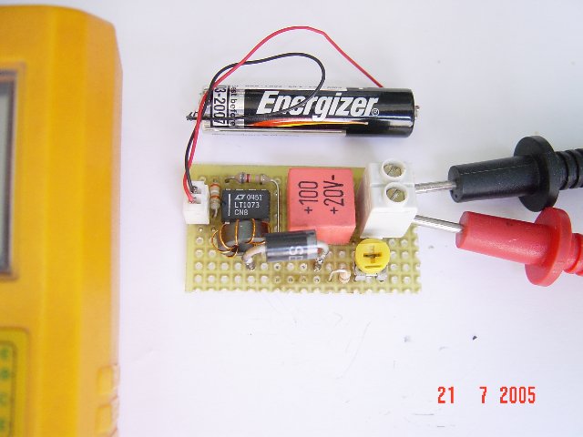
1.5V to 5V/12V DC/DC Converter with LT1073

 1.5V to 5V/12V DC/DC Converter with LT1073 Circuit
1.5V to 5V/12V DC/DC Converter with LT1073
Small 1.5V to 5V or 12V DC/DC converter with LT1073 chip. The IC is available in three different versions, depending on output voltage. Two with fixed output voltage of 5V and 12V, and the most interesting that can be adjusted. The adjustment is done through a voltage divider with two resistors, of mass, output and Terminal 8, internally connected to the voltage comparator IC, which is responsible for stabilizing the output voltage. 
 
1.5V to 5V/12V DC/DC Converter with LT1073

  • Digg
  • Del.icio.us
  • StumbleUpon
  • Reddit
  • RSS

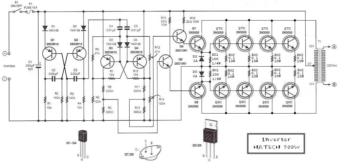
Simple 500W 12V to 220V Inverter

500W 12V to 220V Inverter Circuit Diagram

500W 12V to 220V Inverter Circuit Diagram
 
This is a 500W DC-to-AC inverter circuit diagram which produces an AC output at line frequency and voltage. 12VDC to 220V 50Hz inverter circuit will power 220V or 110V appliances from 12V car battery. The circuit is easy to make and is low cost. Use proper transformer. The output (in watts) is up to you by selecting different power rating transformer and power transistor rating. If you load electronic device which require 120V AC, then use transformer with 120V in output.

  • Digg
  • Del.icio.us
  • StumbleUpon
  • Reddit
  • RSS